


SPECTRUM TO
COMMODORE 1084 CONNECTIONS
All we know that connecting our Spectrum to a TV through RF is not the most
appropriate. A good option to avoid RF output is the use of a TV with SCART.
Another option is to adapt some type of monitor that allows us a clear
visualization of the computer.
In this article we will discuss the connection of any Spectrum model with
the Commodore 1084 series monitors. It is a CRT monitor with excellent
features, which allows the connection of almost any computer model that has
a frequency of 15Khz. Still it's not difficult to get at a reasonable price
in the second hand market.
ABOUT COMMODORE 1084
The 1084 is a monitor equipped with RGB and CVBS video inputs. It is also
equipped with speakers wich we can also connect the audio of our Spectrum.
There are different variations of 1084. All of them have RGB and CVBS
inputs, varying the type of RGB connector they have integrated. First models
are equipped with DIN connectors while the most modern (and perhaps the most
abundant today) use DB9 connectors. These are what we will discuss in this
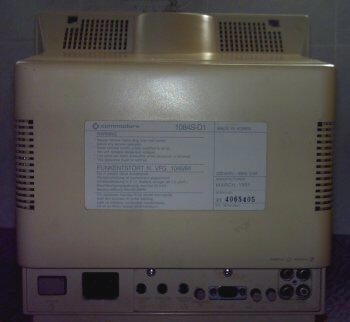
article, the exact name of this model is Commodore 1084s-D1.
 |
 |
1084s-D1
Front
|
1084s-D1
Back
|
The composite video input of this device is the typical RCA connector
that can be found on all types of monitors. These 1084 models also have
stereo sound input through two standard RCA connectors.
|
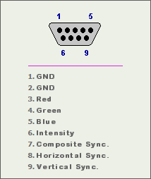
1084s-D1 RGB pinouts
|
SPECTRUM 16/48/+ CONNECTION
Unfortunately, the first Spectrum models do not have composite video
output or RGB. The only option we have is the RF connector for a lifelong
television. One way to connect these models to a 1084 is to make a
composite video output. There are several assemblies to make a composite
video output on these Spectrum:
Microhobby scheme: It is extremely simple to perform, but the
output's quality is not very good. It is simply to take out the video
input that goes to the RF modulator of the Spectrum board through a
resistance of 10 Ohms. As GND we will use the metal housing of the
modulator.
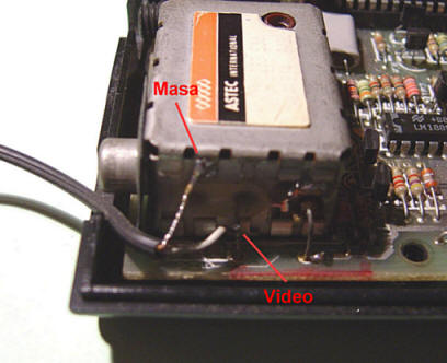 |
| Connectión of video output on
the modulator |
We need an extra RCA output in our Spectrum. You can place a hole drilling
the box, or avoid that great suffering by placing an aerial that goes
outside through the hollow of the RF connector. Doesn't looks very
professional, but avoid's modifying the external appearance of the computer.
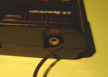 |
External video cable output
|
Regarding the resistor, you can place it directly on the video output of the
modulator or inside the external RCA connector housing, if you have chosen
this option.
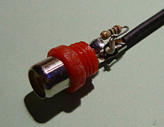 |
Placement of resistance inside the
RCA
|
Sami Vehmaa's Scheme: Something more complicated to do but with much
more quality. It uses three components that can be placed inside the metal
box of the modulator and thus take advantage of the original RCA output
connector, avoiding external modifications of our beloved Spectrum.
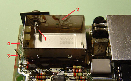
First of all we must remove the plate inside the modulator, for this we must
remove the metal box from the modulator completely. Cut the two wires on the
left and look at the back of the plate, you will see that it is only two
welding points that hold it. Once outside you can remove the bottom cover of
the modulator and remove the board easily.
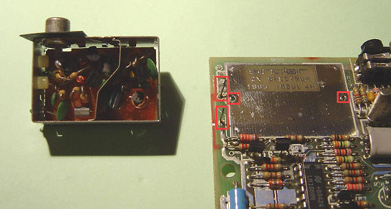 |
| The two wires to be cut and
the welding points of the modulator |
Then put the bottom cover back on and re-solder the box on the board, now it
is ready to be able to freely place the components inside.
 |
| The empty modulator box ready
for our assembly |
Now we will take advantage of this space and the RCA output of the box
itself to build the small assembly based on a capacitor, a resistor and a
transistor.
 |
Spectrum 48 CVBS scheme
|
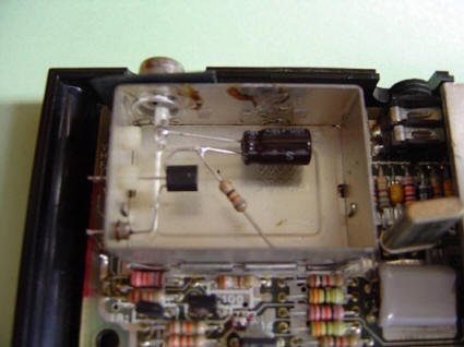 |
An example about how to connect it
|
Once the output is done, we just have to connect an RCA cable to the
video input of 1084.
 |
| A simple video cable with RCA
male connectors |
SPECTRUM + 128
CONNECTION
This model has a DIN connector that allows connection to both composite and
RGB video. There are two different +128 models. Although they have very
similar video circuitry, they have the signas placed on a different way on
the DIN connector.
One is the Spanish model manufactured by Investronica that came standard
with numeric keypad and the other is the English version of Sinclair. The
connection diagrams in this article refers to the Spanish model. For english
models, you only have to change the pin number to the corresponding value of
the connector.
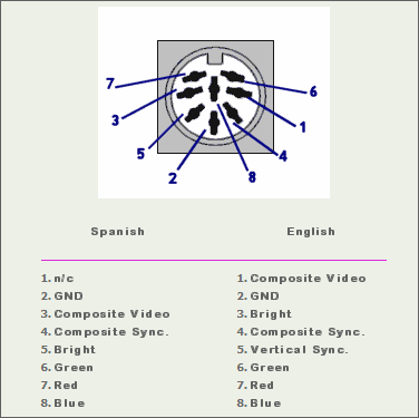 |
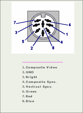
Spectrum + 128 DIN pinouts
|
Video Compuesto: Pretty simple to do. We should only place a 15
Ohms resistor at the output of the composite video signal of the Spectrum.
 |
| Cable for composite video
connection |
RGB: The highest quality. Using this output we can see our +128 with
excellent image quality.
The main problem that we must solve for the connection of this computer is
that we must mix the brightness signal with each of the three colors in
order to see the entire Spectrum palette.
If we look at the connection diagram of the PERITEL connector, we can see
that there is an additional Bright signal.
To be able to mix in brightness with each of the colors we will use only
diodes and resistors. The scheme is as follows:
 |
| RGB Cable Scheme |
This time it will not be very comfortable to build the circuit inside the
1084 connector housing since the space is quite limited. It can be done at
the output of the DIN connector housing cable by soldering the diodes and
resistors and isolating them from each other.
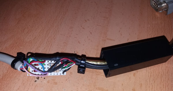 |
| The scheme implemented on the
cable |
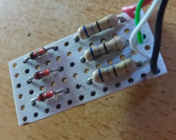 |
Detail of the scheme
implementation
|
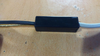 |
| Final aspect |
SPECTRUM +2 CONNECTION
This model has a video circuitry very
similar to that of 128, although the available signals from the connector
change their positions.
 |
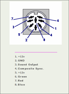
| Spectrum +2 DIN pinouts |
Composite Video: Same as Spectrum 128.
|
| Spectrum +2 scheme for
Composite video |
RGB: The main difference is the brightness signal, although still
present in the connector, now is already mixed with the three colors so
that the construction of the cable is pin to pin.
 |
| Spectrum +2 scheme for RGB |
SPECTRUM +2a/+3 CONNECTION
These models do not have composite video
output, but all have RGB with which we will achieve a perfect image
quality on our monitor.
 |
| Spectrum +2a/+3 DIN pinouts |
Fortunately, they also have the brightness signal mixed with the colors, so
we avoid the work of having to do it ourselves, but this time we must add a
resistor to each color pin of the connector to reduce its intensity a bit.
 |
| Spectrum +2a/+3 scheme |
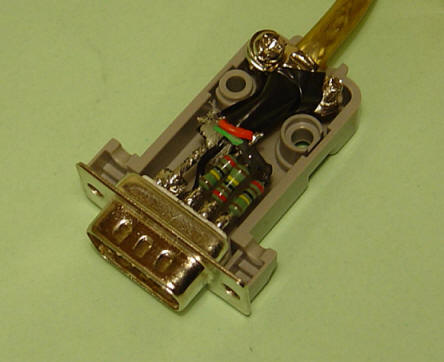
|
| The resistors inside the DB9
connector of 1084 |
Note for +2a/+3: The sync signal
is somewhat more problematic in recent models of Amstrad. For some 1084
monitors, especially the latest models, the intensity of that signal is
somewhat low, so we only get an unstable image that never stays still on
the screen. The problem is a 470 Ohm resistor that is placed just at the
exit and is a bit high for some 1084 needs.
If this problem appears, you must replace the resistor with one of a
slightly lower value. A 390 Ohms resistor will be enough to solve it.
To change it open your Spectrum and locate the R34 resistor on the board
(right of the modulator) and replace it with the 390 Ohm.
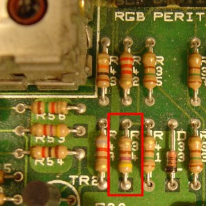 |
R34 position on +2a / +3
|


