


Many of us who at some point have connected our +3 to an amplifier have
realized the terrible sound quality of this machine. In fact, if we
compare it with the +2 or 128k sound output, the difference in quality is
remarkable. The problem in an error in the implementation of the sound
circuitry of the first +3 models.
The solution is based on replacing the original sound circuit with a new
one that will provide an ACB stereo output that will substantially improve
the sound quality of the equipment.
The error is found in the first version of the motherboard (+ 3A). This has a very bad and distorted sound quality. The second version (+ 3B) has the bug fixed but the output is still mono. The corresponding version will be printed on the top of the plate:
The screen printing of the board components varies between diferent versions. Throughout the entire article the screenprint of + 3A will be used. The only differences in names found in this article are the following:
| +3A | +3B |
| C38 | C201 |
| R42 | R208 |
| R43 | R207 |
| R72 | R200 |
If you make this modification in a + 3B replace the names used by its corresponding in the table. Its located inside the board on a similar location, except R200 which is next to one of the keyboard ribbon connections. All other operations will be identical on both revisions.
Remove the computer motherboard to start. First we must cut some tracks:
 |
| IC11 track cuts |
Pins 1,4 and 5 correspond to the three sound channels that the AY-3-8912
can generate simultaneously. With this we will be able to break the union
of the outputs of the three channels that turned the sound into mono. It
will be here where we will connect the new sound circuit.
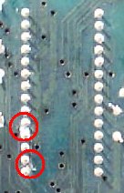
We must also remove some other components:
 |
| Capacitor C38 |
|
| Resistor R72 |
With these modifications we managed to isolate the original sound circuit from the outputs of the AY chip.
 |
| Circuit Diagram |
 |
 |
| Printed
circuit (component side) |
Printed circuit (solder side) |
 |
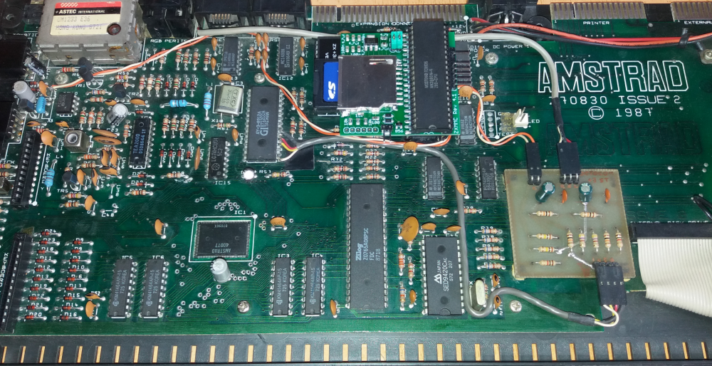
| Circuit ubication inside +3 |
Now we must connect the sound input of our circuit to the sound output of
the AY. We need the 3 integrated signals and ground.
We will connect pins 1,4 and 5 to the corresponding inputs of our circuit.
The best solution is to solder directly over the chip pins on the
components side. We will use pin 6 of the integrated as the ground for our
circuit. These are the only soldering we will have to do with a little
more care.
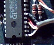 |
| AY output connections |
At this time any sound generated by the AY will enter our circuit directly, but we still have to introduce the BEEP in our circuit. To do this, we will connect the input marked BEEP in the connection diagram with C37 capacitor.
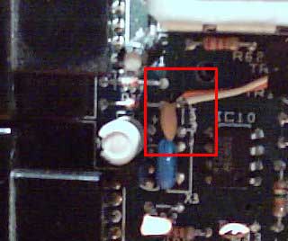 |
| C37 capacitor connection |
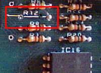
Originally there is a unique audio output signal for a mono output. We need another pin to divide the output into two channels and fortunately the 12v signal is repeated so we can perform the output without losing any of the original connector signals. The operations to modify the RGB / PERITEL are the following:
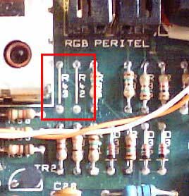 |
| Resistors R42 and R43 |
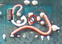 |
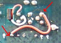
| RGB track cuts |
 |
| R44 to RGB pin 5 |
 |
| R44 to RGB pin 1 (solder side) |
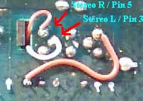 |
| RGB/PERITEL connections (solder side) |
Here we can see the original pinout of the connector and the result once the modifications have been made.
 |
 |
| RGB/PERITEL Original | RGB/PERITEL Modiffied |
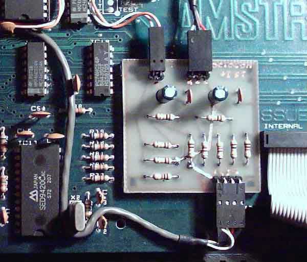
Final aspect of the board with the new audio circuitry installed.
 |

| Website
hosted on Speccy.org |
Contact with us |
 |
 |