


The objective of this modification is to provide a quality ACB stereo sound at +128 and integrate its output into the original RGB/PERITEL connector avoiding any modification on the original case. The solution is based on replacing the original sound circuit with a new one that will substantially improve the original sound quality of the equipment.
In this article we will discuss the Spanish version developed by Investronica (board rev. 2 & 2-1). The English version can also be modified with the same circuit but the modifications in the motherboard as well as in the RGB/PERITEL connector are different.Remove the computer motherboard to start. First we must cut some tracks:
 |
| IC32 track cuts |
Pins 1,4 and 5 on IC32 correspond to the three sound channels that the AY-3-8912 can generate simultaneously. With this we will be able to break the union of the outputs of the three channels that turned the sound into mono. It will be here where we will connect the new sound circuit.
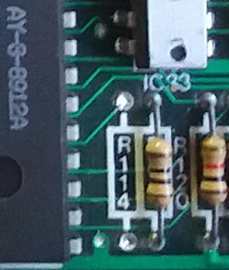 |
| Resistor R114 |
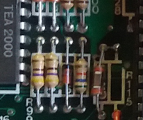 |
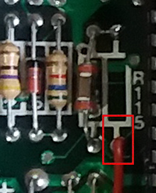
| Resistor R115 |
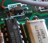 |
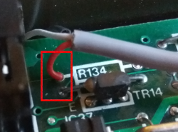
| Resistor R134 |
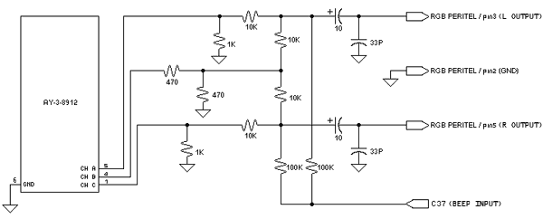 |
| Circuit diagram |
 |
 |
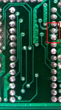
| Printed
circuit (component side) |
Printed
circuit (solder side) |
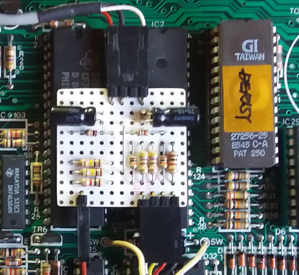 |
| Circuit ubication inside +128 |
Now we must connect the sound input of our assembly to the sound output
of the AY. We need 3 integrated signals and ground.
We will connect pins 1,4 and 5 to the corresponding inputs of our
assembly. The best solution is to solder directly over the chip pins on
the components side. We will use pin 6 of the integrated as ground for our
circuit. These are the only soldering we will have to do with a little
more care.
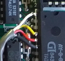 |
| AY
output connections |
At this time any sound generated by the AY will enter into our circuit directly. To add the BEEP signal we will connect the input marked as BEEP in the connection diagram with the output of the resistor R115 previously removed.
 |
| R115 resistor connection |
 |
 |
| Right
output connection |
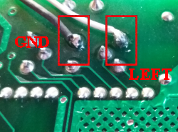
GND and Left output connection |
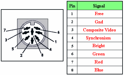
Here we can see the original pinout of the connector and the result once the modifications have been made.
 |
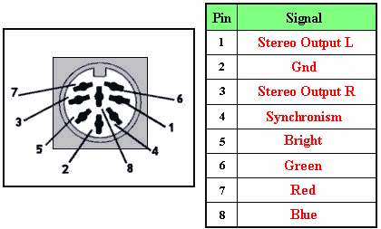 |
| RGB/PERITEL Original | RGB/PERITEL Modiffied |
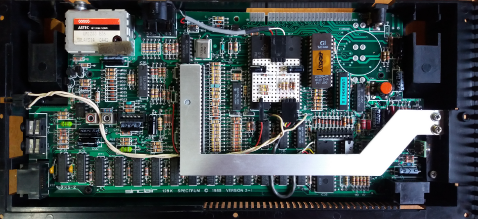
Final aspect of the board with the new audio circuitry installed.
 |

| Website hosted on
Speccy.org |
Contact with us |
 |
 |